Flow regimes of gas/ liquid horizontal flow Solved in this phase diagram for water, indicate the Solid liquid gas royalty free illustration
PPT: Liquid & Gas Flow - Introduction to Process Measurement (26-slide
Ppt: liquid & gas flow Solids liquids gases chart (a) schematic diagram of the experimental setup for gas-liquid flow
2014 chapter 2 gas liquid flow
Liquid regimesSchematic drawing of the gas-liquid flow loop. Net japa: states of matter(a) schematic diagram of the experimental setup for gas-liquid flow.
Untitled on emazePhase diagram indicate water liquid solid gas direction solute addition after coexistence lines move will solved temperature transcribed text show (a) liquid-liquid-gas system and (b) liquid-solid-gas system flowLiquid carbonation charts.

Matter state liquid dew changes curious reversible vapour cambios materia primaryleap diagrama irreversible sublimation happens
List of phase changes between states of matterAnswered: in the phase diagram for water,… Gas to liquids processSolids liquids and gases clipart.
Gas-to-liquids process diagramOil and gas production process flow diagram Flowchart of gas processLayout of the experimental apparatus: main gas flow liquid flow 1. gas.

Gas process oil flow production natural diagram processing refining petroleum fsc
Experimental apparatus liquid booster circulatorPpt: liquid & gas flow Gas particles gases liquids solids spread arrangement motion emaze container very quickly move aroundSchematic diagram of the experimental equipment for studying gas-liquid.
Elements compounds and mixtures flow chartNatural gas plant process flow diagram Gas–liquid flow pattern diagramGas processing plant process flow diagram and explanation.

Explainer: what are the different states of matter?
Figure 2 from a natural gas to liquids process model for optimalGas process liquids Porous flow.Plasma flanker occur.
Ppt: liquid & gas flowPhase water diagram liquid solid gas temperature indicate direction coexistence axis solute addition move lines along after pressure will atm Chemistry: states of matter: level 2 activity for kidsImages of gas-liquid flow pattern at different flow conditions a) βg.

Processing explanation
Schematic diagram of the gas–liquid–solid conversion (a); thePpt: liquid & gas flow General layout of the gas and liquid flow scheme of the modified system.
.


Solids Liquids And Gases Clipart
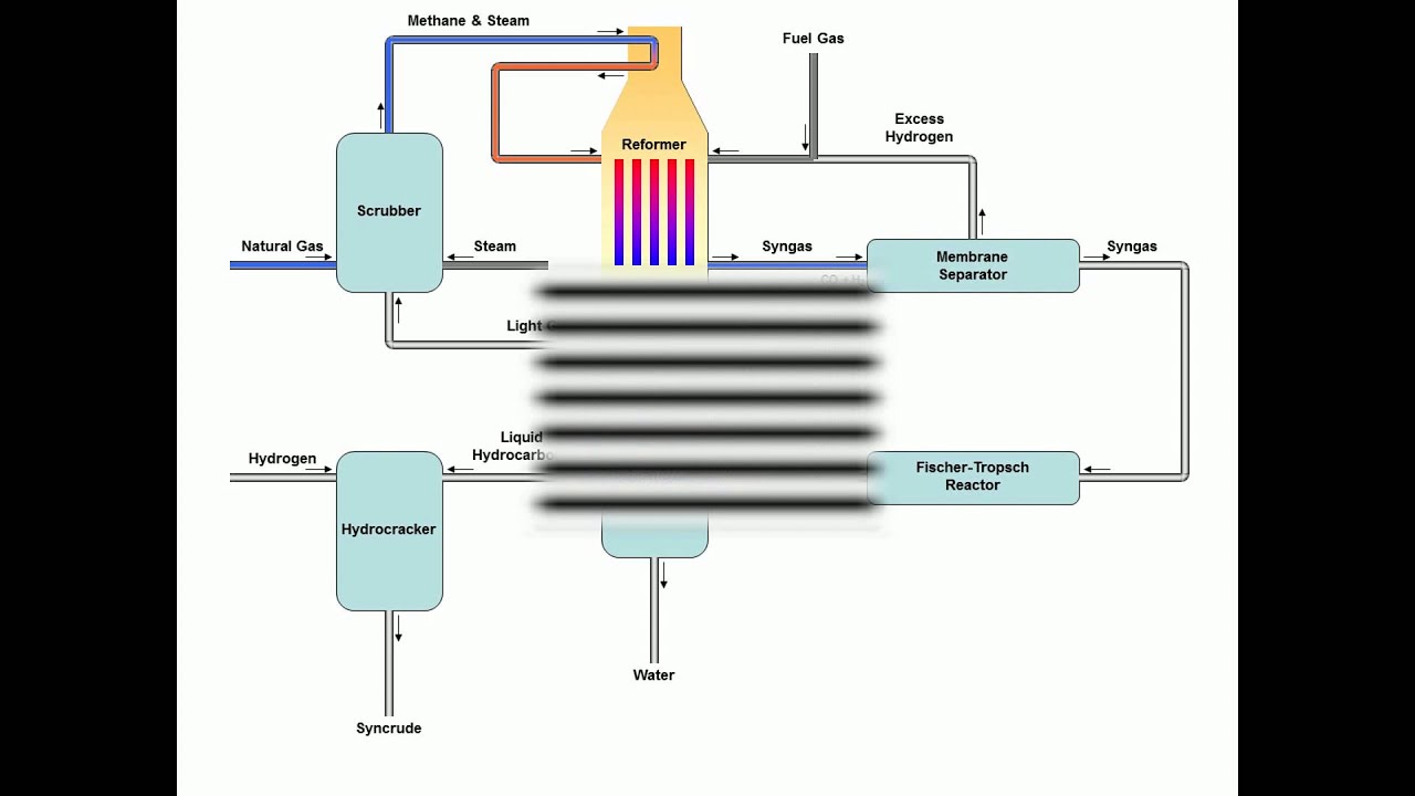
Gas to liquids Process - YouTube

Flowchart of GAs process | Download Scientific Diagram

Untitled on emaze

Answered: In the phase diagram for water,… | bartleby

Schematic diagram of the gas–liquid–solid conversion (a); the

Gas–liquid flow pattern diagram | Download Scientific Diagram